 ≤ ξ0ST and p ≳ pc as discussed in
Sec.3.6.
This simulation is here again presented to illustrate code capabilities for a realistic magnetic configuration and a hot plasma. The problem addressed corresponds to fast electron losses in magnetic ripple, between two consecutive toroidal magnetic field coils. The case studied correponds only for the Tore Supra tokamak, which exhibits a very large magnetic ripple on the outer plasma edge, of the order of 7% [?]. Though the description of the physical process is not fully consistent with the basic assumptions of the code, and the bounce-averaged theory especially, calculations are expected to give valuable informations of the loss rate profile.
Simulations parameters are exactly those used in Sec.7.5 for fast electron transport studies,
except that the magnetic configuration corresponds to the tokamak Tore Supra which has a
circular plasma cross-section, and that fast electron radial transport is here neglected. Moreover,
the magnetic ripple losses are modelized by a characteristic loss (drift) time νdST-1 = 1000
inside the supertrapped domain bounded by  ≤ ξ0ST and p ≳ pc as discussed in
Sec.3.6.
Temperature and density profiles used as input for the magnetic equilibrium calculations done by HELENA code are presented in Fig. 7.38. As usual in current drive regime at low density, the electron temperature profile is peaked, and its value is much larger than ion temperature. The dominant ion (deuterium) profile is determined selfconsistently from the electron density and effective charge profiles, the latter being taken flat at a level of Zeff = 1.5. In the calculations which are based on electroneutrality, only one fully stripped impurity is considered, i.e. carbon Zs = 6, in order to avoid the use of an impurity transport code. The resulting 2 - D contour plot of the magnetic poloidal flux surfaces is given in Fig. 7.39, where the Shafranov shift is clearly visible. Here, calculations are performed for a monotonic safety factor profile, like for the JET case discussed in the previous section.
cmcmcm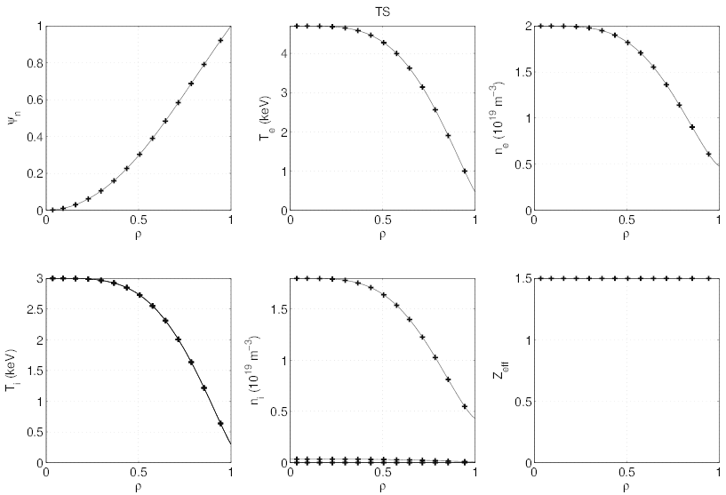
cmcmcm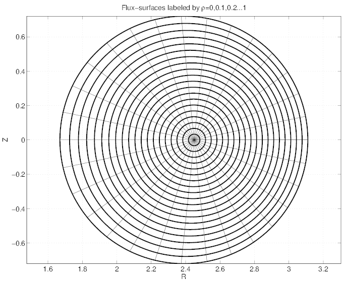
In order to be concerned by more energetic electrons in this simulation, the Lower Hybrid
quasilinear resonance domain is slightly at higher energy, i.e.  , with the same
radial profile dependence of D0,newLH
 as discussed in Sec. 7.5. The RF power
absorption takes place close to ρ ≃ 0.4 as shown in Fig.7.40. In this case, the current
density and RF power absorption profiles are aligned, since the physics is basically local
(slowing-down).
cmcmcm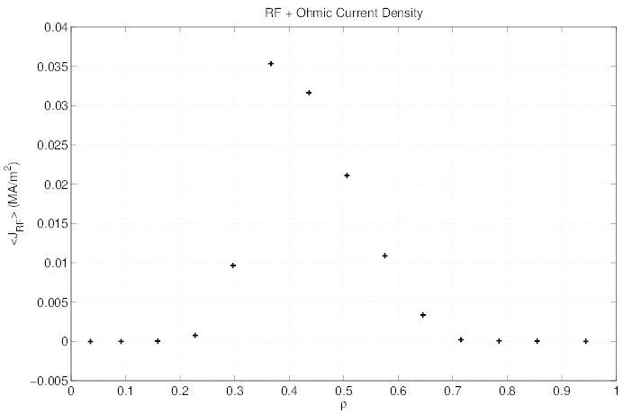
As shown in Fig. 7.41, the fact electron loss rate exhibits a clear peak at ρ ≃ 0.7, as observed experimentaly. The 3 - D calculations reproduce therefore correctly the profiles given by previous studies with a 2 - D Fokker-Planck code [?]. In addition, the two methods used to evaluate the magnetic ripple loss rate profile, as discussed in Sec.3.6 gives very similar quantitative results, that makes the code very reliable concerning this problem.
cmcmcm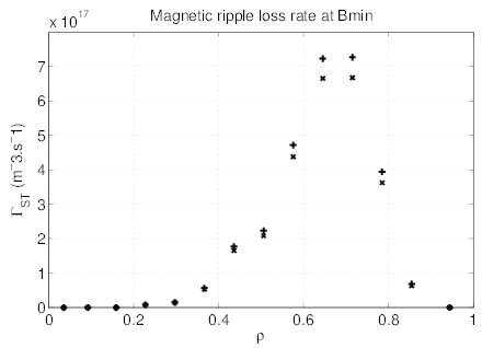
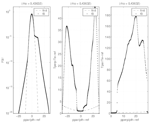
The detailed dynamics in momentum space is given by the 2 -D contour plot. As shown in
Fig.7.42 at the radial position ρ ≃ 0.44, the supertrapped domain defined by  ≤ ξ0ST in
which electrons are considered as lost lies well inside the domain where electrons are trapped
 ≤ ξ0T . The collisional detrapping threshold is approximately pc = 5 at the local density here
presented. The effect of the magnetic ripple losses may be clearly seen on the distribution
function f0
 which drops dramatically above pc provided
  ≤ ξ0ST . It is important to show
that outside from this domain, the electron distribution function is nearly similar to the one
without magnetic ripple losses. This is particularly clear in Fig.7.43. This confirms that losses
are very small, and this is the reason why the code remains globally conservative at each radial
location.
cmcmcm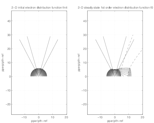
cmcmcm